Building of electrical installation for light (1/2)
Part 1: Power cables and installation materials
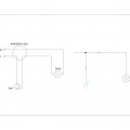
In this article I will try to give the most common multi-line and single line diagrams for managing electric lighting (lamps) with installation keys. In multi lines diagrams it is showing all wiring and junction boxes. It can be said that they are more close to the mounting schemes. Single line diagrams are used in the drawings as they are drawn standardized symbols for switches, boxes and luminaries such as the number of conductors is shown with cross lines on a line symbolizing all conductors. You have to check compliance with standards and regulation in you country. In my country lighting installations in accordance with Regulation 3/09.06.2004 run directly hidden under plaster or laid in cable ducts. Under Article 1929 of Regulation 3 to power lighting systems for general lighting it uses wires with copper conductors and a cross section less than 1 mm ². Also according to Article 1876 lighting circuits shall be sized and protected by fuses or circuit breakers for the operating current not exceeding: for industrial and public buildings – 25A for residential and other buildings where maintenance of the lighting system is not performed by a specialist – 16A;
Switches, cables, junction boxes and connectors
There is widest variety of electrical switches for lighting control. Manufacturers offer different looks formed from simple to luxurious series. Each manufacturer provides user manual for wiring them. Here they will not be considered.
The cables that are used depend on the way of mounting them, and the type of performance of the installation. Most often these systems are implemented hidden under the plaster in the corrugated pipe or directly placed under the plaster, depending on the structure of the premises (for example, plasterboard or brick).
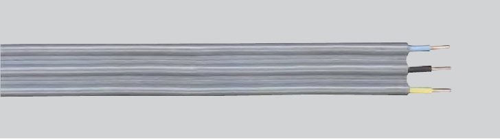
When cables are laid directly in the walls it is used cable type PVV-MB1 or NYIFY. The difference between the two cables is that one is made by Bulgarian standard BDS 904-84 and the other by German standard DIN VDE 0295, IEC 60228. The cable can be attached to the walls with plastic anchor that have cable tails or plaster used for initial fixation. Cable is flat and it is for fixed installation. The maximum permissible operating temperature is +70 ° C, while the nominal voltage is 220V/380V. Its installation on place can’t be done at temperatures lower than -5 ° C.

Electrical cable type PVV-MB1
More technical details for cable PVV-MB1 and possible combinations of number of conductors and cross-sections can be found here.
Electrical cable type NYIFY
More technical details for cable NYIFY and possible combinations of number of conductors and cross-sections can be found here.
When laying the cable is done in corrugated tubes, such as walls of gypsum board and cable trays above the suspended ceiling it is using cable flexing type SVT or NYM. The first cable is manufactured by the Bulgarian standard BDS 904-84 and the second by the German and international standard DIN VDE 0295, DIN VDE 0250, IEC 60228. Withdrawal occurs in flexible corrugated PVC pipe whose size is consistent with the number and diameter of the laid cable. Cable is circular. The maximum permissible operating temperature is +70 ° C, and rated voltage is 300/500V for NYM and 0,6 / 1kV for SVT. Its installation on place can’t be done at temperatures lower than -5 ° C.

Electrical cable type SVT
More technical details for cable SVT and possible combinations of number of conductors and cross-sections can be found here.
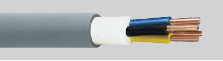
Electrical cable type NYM
More technical details for cable NYM and possible combinations of number of conductors and cross-sections can be found here.
Distribution (junction) boxes, in which became the wiring of lighting fixtures and control keys are generally two types – concealed or surface mounting (with mounting and cable trays). There is great diversity in form and execution – round, square and rectangular. Some of the types are shown in the following figure.
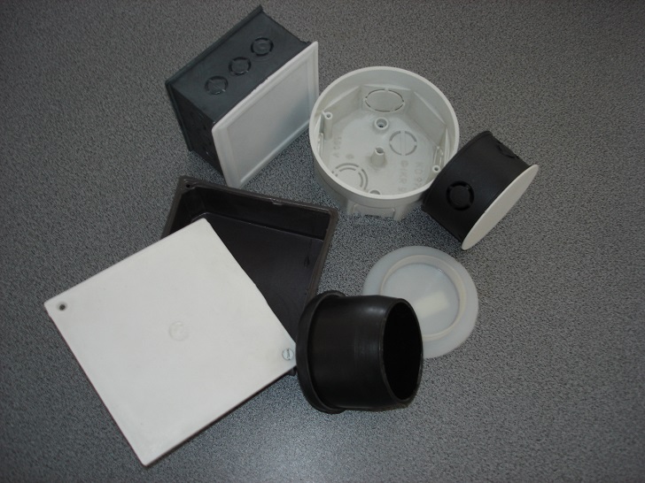
Different types of distribution boxes
In distribution boxes shall be connection of already laid electric cables. In older plants often used a method of directly connecting the wires by twisting – zachistva cable is stripped about 1 inch and two wires are twisted to each other by means of pliers and then the end is cut off, than isolated using PVC tape. We will not dwell on the debate about the correctness of that connection, but it could be argued that the practice is sufficiently proven its reliability. Obvious disadvantiges of this compound is that it is not suited for repairing and doesn’t allows multiple connections.
In modern plants for the connection of electric wires are used terminals. Mainly used screw terminals, depending on the insulator are bakelite, porcelain or polypropylene. Standard sizes and most often used in lighting installations are for conductors 2.5 mm ², 4 mm ² and 6 mm ², the electric contact is provided by a screw through which copper conductors are compressed.
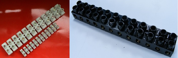
Polypropylene and bakelite screw cable terminals
Porcelain terminals are for wire cross section 2.5 mm ² and a voltage up to 380V.
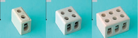
Porcelain cable screw terminals
There is also the so-called installation coupler, which is a porcelain base with clamps on her, and it has the ability to connect two conductors up to 10 mm ² / 380V. There are five clamps on each base. Actual installation coupler is mounted in a distribution box.
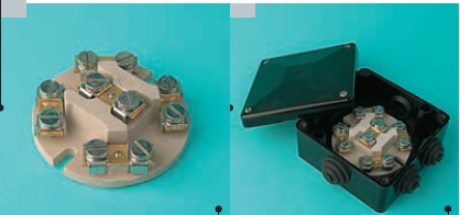
Installation porcelain screw coupler
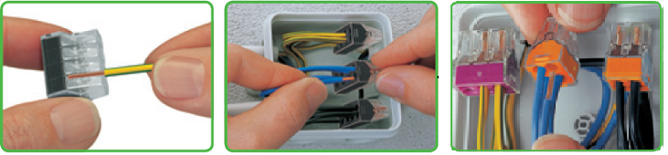
In the current lighting and power systems are used so-called free screw connectors. Here would be given an example of a manufacturer’s products WAGO. Of course there are other manufacturers in the market. Their price is generally cents (0.5 -0.6 lev) and becoming less and attractive. Their squeezing was performed by the plate under pressure or a lever system. It si easy to made multiple connections/disconnections with them and they are very comfortable to use. There are terminals for cables with cross-sections from 0.75 mm ² to 4 mm ², depending on the model there is terminals for solid conductors as well for stranded wire or for connection of two different conductors (solid and stranded)
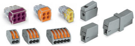
Some types of WAGO connection terminals for junction boxes
The following figure shows connection of two types of terminals with lever and pressure.
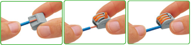
More technical details on the size and tests they are subjected to, standards and technology screwless terminals WAGO can be found here.
In the next part of this article will describe how to connect and control of electric lighting in switchgear (switches and relays)