Building of electrical installation for light (2/2)
Part 2: Schemes for control of lighting (lamps) by electrical switchers
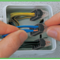
Scheme 1: Control of luminaries (lamps) from simple switch
Phase conductor (L) is disconnected by power switch (Sw1), connections are made in the junction box (distribution box). When you closed the switch Sw1, the power circuit is closed and the light (lamp) lights up.
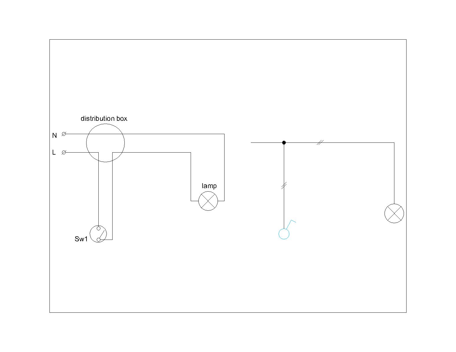
Scheme 2: Control of luminaries (lamps) from serial (double) switch
In case of serial key from one place you can control two groups of lamps.
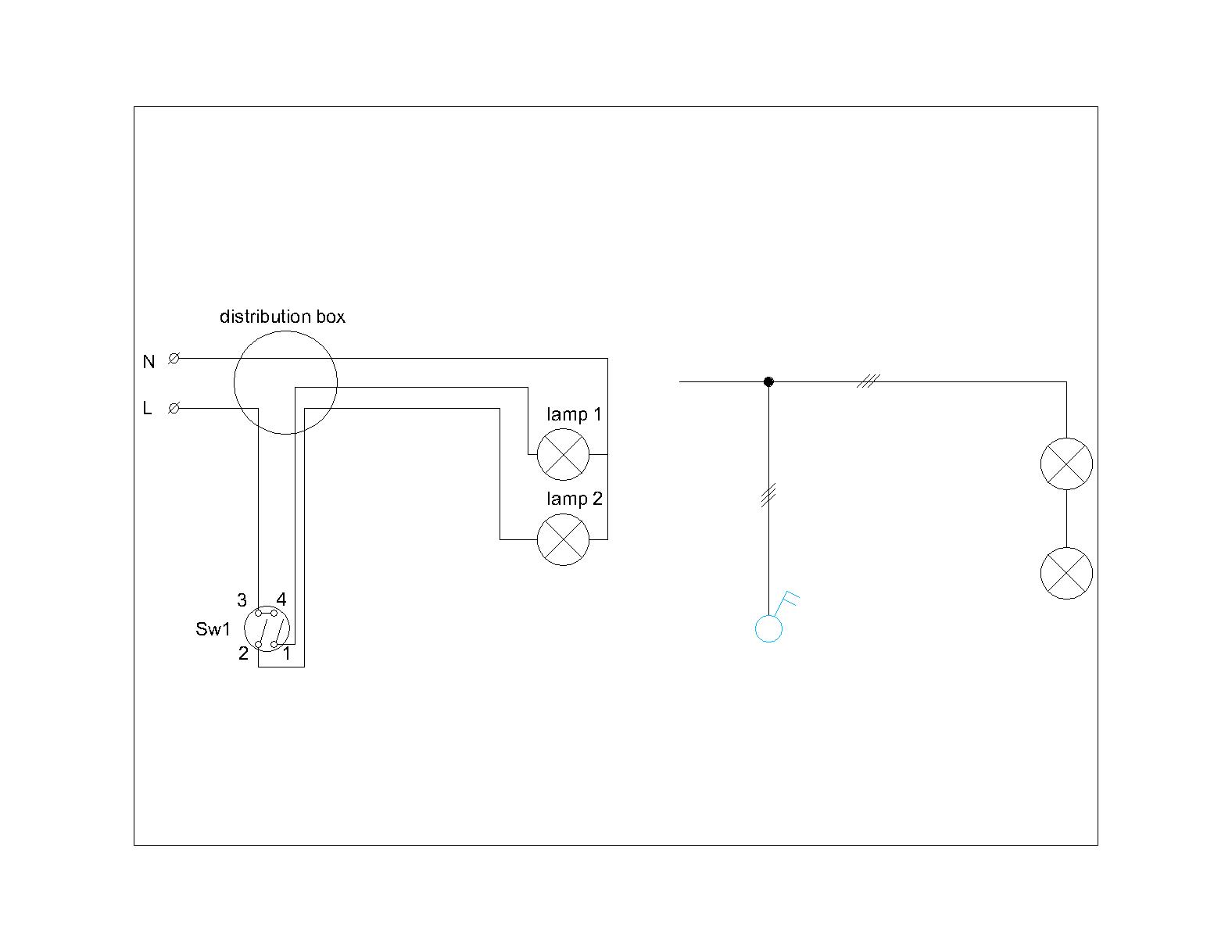
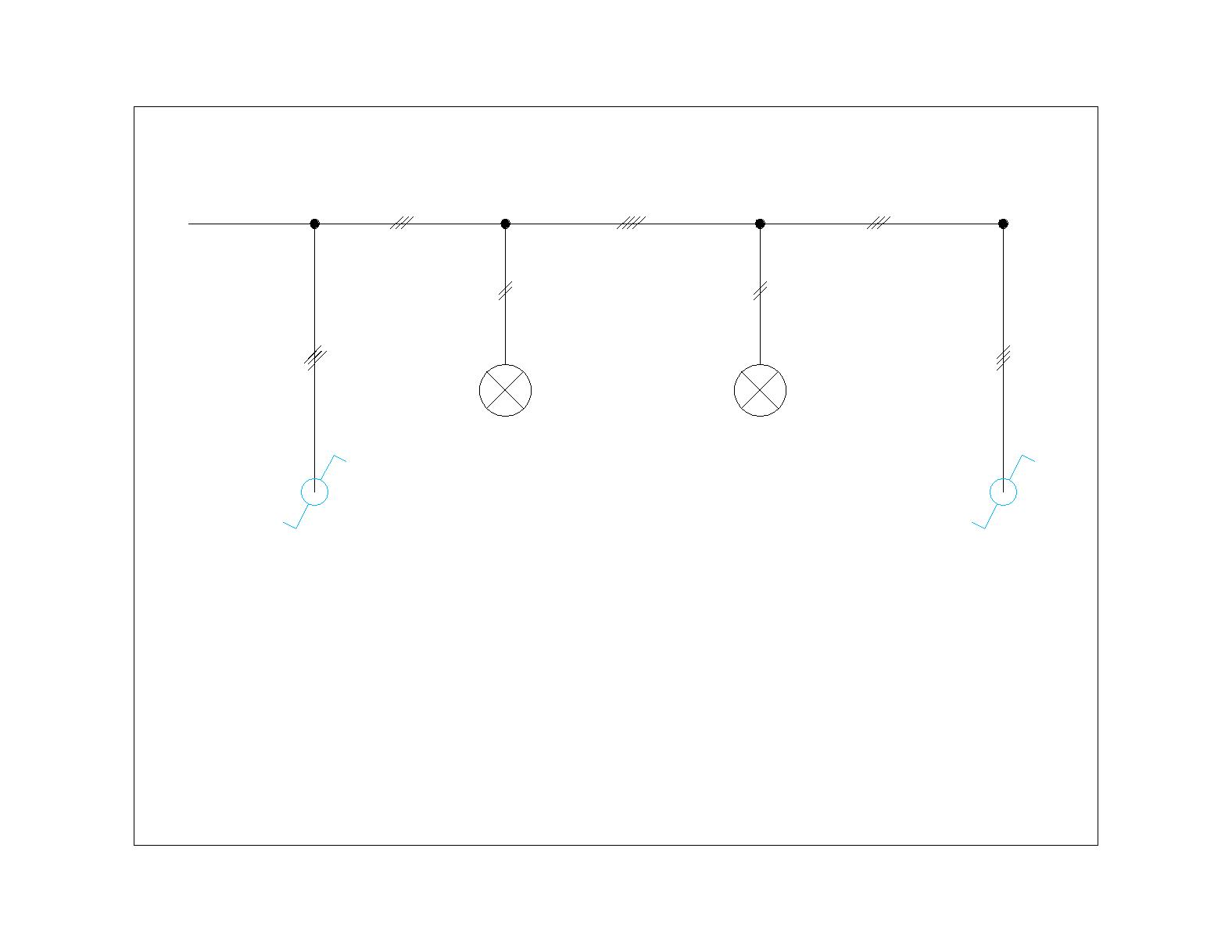
Scheme 3: Control of lamps from two-way switch
Two-way connection scheme is used when you need to control lamps in different places, such as corridor where from one place you have to switch on the lamps but from another you have to switch them off. Note the exchange of terminals 2 and 3 of the two keys (2 from Sw1 connects to 3 from Sw2 and vice versa). This is done for esthetic reasons – when it is done the two keys have the same position after switching on then off the lighting circuit.
And this is its single-line diagram:
When the distance between the two keys is not great you can use the same junction boxes to power the lamp.


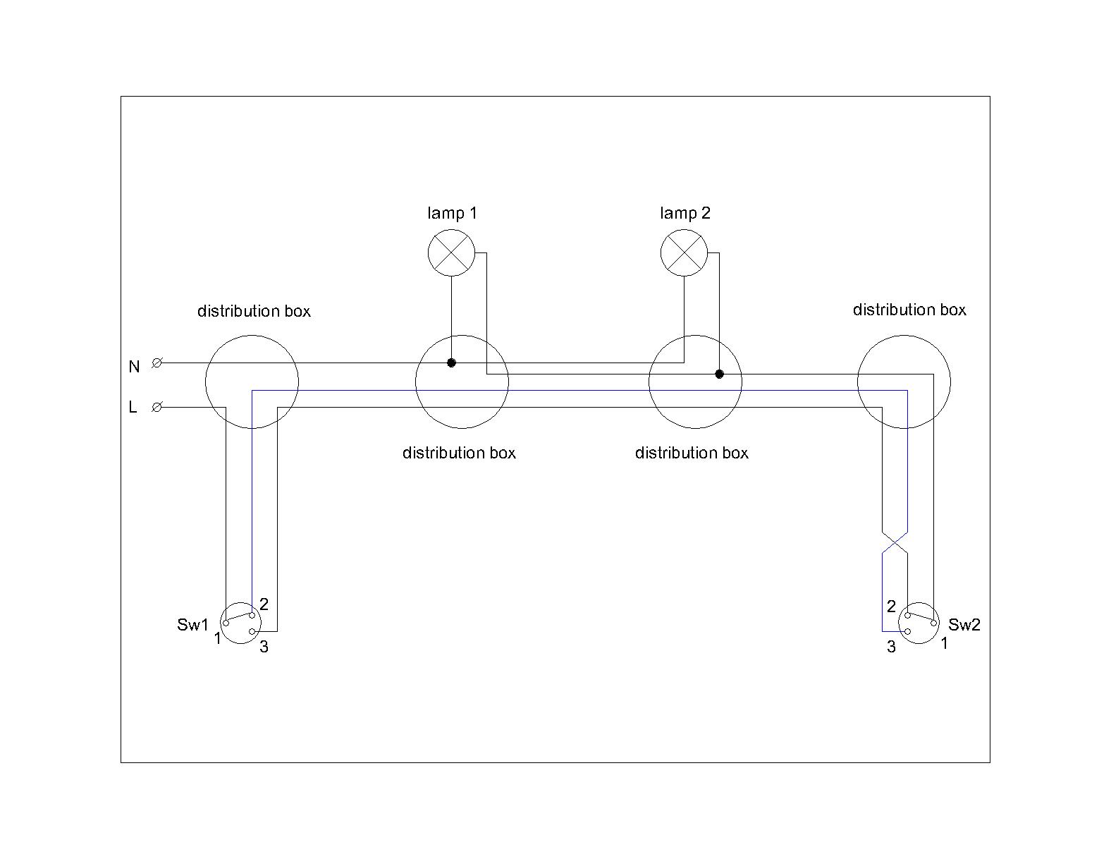
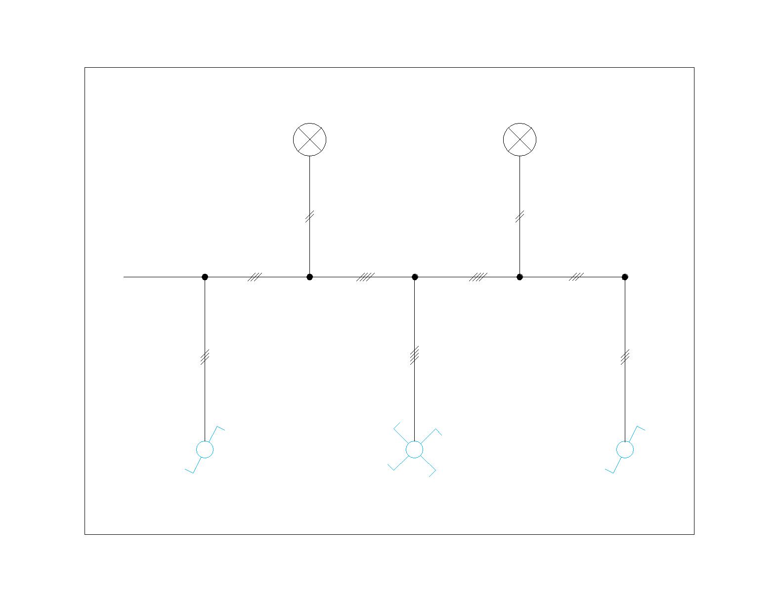
Scheme 4: Control of lamps from the two-way switches and intermediate (cross) switch
Scheme with control of luminaries by the intermediate (cross) switches are used where it is necessary intermediate control between the two two-way switches – such as staircase or hallway floors with connecting doors along it. Can be added as many as the number of intermediate switches are necessary in keeping with the rule of crossing wires (green and blue lines)

Accordingly, the single-line diagram of a cross and two two-way switches is:
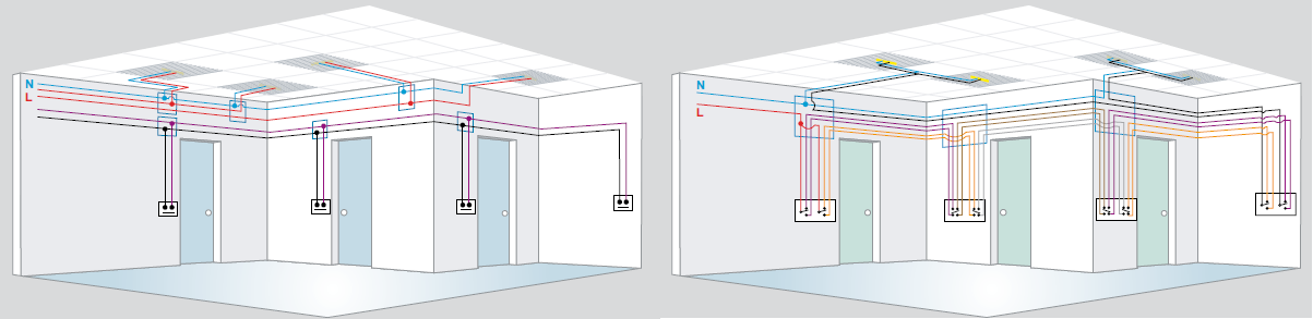
When the number of intermediate switches is going too big, scheme is complicated. The same scheme can be implemented with pulse relay. This simplifies connections and eliminates the two-way and intermediate (cross) switches – for control are used light buttons. Required number of wires is also minimised and it is easy to add additional light buttons (control circuit is divided by power). The pulse relay can be mounted in a floor distribution electrical board, if there is no such board it can be mounted in small one unit electrical board at the beginning of the room (hallway, stairs).
A comparison of the electrical plant done with pulse relay and the same installation performed by intermediate (cross) and two-way switches in the conventional way can be viewed in the following figure:
All reputable manufacturers have in their product range switching pulse relays for remote control. Here in the article will be examined this particular type TL impulse relay 16A or 32A manufactured by Schneider Electric company. More specific catalog data can be found here.
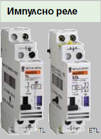 Installed under the protection devices chain in lighting circuit. Allows a large number of switching and the possibility to add more functions with auxiliary devices (time delay, step control, illuminated switch, motion detector, etc.). In case of emergency there is an option for manual switching by the handle to the front of the relay, and also it is provided a mechanical switching indication made by the position of the handgrip. The noise level is less than 60dB from a distance of 1m.
The selection of In of a TL becomes from tables specified by the manufacturer. This is necessary because of wide variety of lamp types and their parameters – starting current, heater current, end-stage failure and others. For example, for the simplest case – bulb lamps, the impulse relay TL16A can directly manage 40x40W, 25x60W or 16 × 100W. When the power of circuit exceeds 1500W, it is necessary to use an extra CT contactor. For fluorescent lighting with electronic ballast the impulse relay TL16A can directly manage 80x18W, 40x36W and again for power greater than 1550W CT contactors are used.
Full range of lamp types and capacities that can be controlled by TL impulse relay with / without contactor CT can be found here.
The wiring scheme of the impulse relay lighting control circuit is shown in the figure below. With purple color is colored the control circuit.