Design of Structured Cabling Systems

Categories/Classes in SCS
1.Cooper phisical layer– shielded and unshielded.
- Category 3/Class “C”
- Category 5е/Class “D+”
- Category 6/Class “E”
- Category 7/Class “F”
TIA and ISO comaprison of frequences, categories and classes are shown in the next tabel: Tabel 1.
| Tabel 1: TIA and ISO clasification according to frequency bandwidth | ||||
|---|---|---|---|---|
| Frequency Bandwidth | TIA (Components) | TIA (Cabling) | ISO (Components) | ISO (Cabling) |
| 1 – 100 MHz | Category 5e | Category 5e | Category 5e | Class D |
| 1 – 250 MHz | Category 6 | Category 6 | Category 6 | Class E |
| 1 – 500 MHz | Category 6A | Category 6A | Category 6A | Class EA |
| 1 – 600 MHz | n/s | n/s | Category 7 | Class F |
| 1 – 1,000 MHz | n/s | n/s | Category 7A | Class FA |
2. Main protocols over cooper phisical layer.
Tabel 2 gives a brief look for cabling and main aplication over cooper phisical layer up to 100 m.
| Tabel 2 : Applications using cooper cabels | |||||
|---|---|---|---|---|---|
| Category 5e Class D |
Category 6 Class E |
Category 6A Class EA |
Class F | Class FA | |
| 4/16 MBPS Token Ring | x | x | x | x | x |
| 10BASE-T | x | x | x | x | x |
| 100BASE-T4 | x | x | x | x | x |
| 155 MBPS ATM | x | x | x | x | x |
| 1000BASE-T | x | x | x | x | x |
| TIA/EIA-854 | x | x | x | x | |
| 10GBASE-T | x | x | x | ||
| Broadband CATV | x | x | |||
3.Optical phisical layer–multi-mode and single-mode.
- OF- 300
- OF- 500
- OF- 2 000
- OS
Advantages of SCS
1. Integration
- Transportation of data, voice and video through one media.
-
Allows integration and manadgment of others systems – BMS, CCTV , Security alarms, Fire alarms.
-
Centralisation of managment and comutation in data racks.
-
Allows more than one protocol simultaneous to be used .
-
Allows optical and cooper cabels on the same network to be used.
-
Supplying the customers with a reserve electrical power supply from UPS on the same cabel trace – shilded SCS and a distanse between power and information cabels according to EN50174.
2. Universality
- Ensure the working of active equipment from different vendors.
- Standard components are used.
- Standart outlets allow to connect different kind of equipment to them.
3.Reliability
- Ensure the working of several generations computers and network equipment.
- Leading suppliers of passive elements for SCS give up to 25 years warranty.
- Easy and complete administration setup and maintenance.
International standards for SCS
Designing, building and administration of SCS use three main standards and guides:
- International: ISO/IEC 11801: 2002 , 2 ed . Information technology.
- United States : ANSI/TIA/EIA-568-A/586-B Telecommunication standards of cabel sysytems in commercial buildings.
- European: EN 50173/A1:2000 Infofmation technology- Generic cabling systems. EN 50174: Planing and Instalation of SCS.
Design of SCS
Designing in our country takes three or four stages according regulations – an Investment Project, Technical Project, Work Project and Executie Project. The Work Project is the basic document describing one SCS before beginnig of mounting and instalation scope. Well designing allows SCS to be installed by more then one independent firms. The technical documentation includes:
- Technical design .
- Distribution of working places at floors.
- Campus connections and traces.
- Schme of earting and bounding of SCS.
- Schme of location and position of Racks in telecommunication rooms.
- Scheme of equipments inside the racks(panels, management, power etc.)
- Scheme of elements in working places .
- Vertical and Horizontal cabel plans .
- Scheme of electrical plant with UPS ( Uninterruptible Power Supply ) if there is one.
- Schemes of electrical distribution boards: electrical and mounting.
- Scope of components and labor.
Active equipment in SCS(LAN equipment)
Well designed and installed SCS allows an acitve equipment to be used, that have more requirements about parameters like QoS, Bandwith, Capacity(LAP) and Security.
- VoIP – using of Ethernet and Internet to deliver voice services (telephone system) with the same equipment for Internet and Voice. This saves to users subscription fees and fees per minute for talks within the company. Only you have to pay is ISP’s fee.
- VPN – connection of two (or more) offices of one company through coded link (PPtP,IPsec). From the side of user they work like they are in the same ofice and share the same LAN’s resources
- Backbone – well designed and builded SCS has high speed backbone connections between main aqtive equipment and servers(File, SAN and others) using LAP or other mener. Capacity of data speed is of the order of gigabits per second. In addition SCS can be separated in several singel Ethernet networks ligicaly with using of VLANs – thats add more efficient and flexibility in managing of network recources.
- Wireless Ethernet – adding an AP ( Access Point ) to the SCS ensures wireless cover in the area with standards Ethernet 803.11 а/ b / g . It is appropriate where it has a lot of mobile users or there isn’t other way to connect equipment with wires.
Main places of equipment and elements of SCS
They are :
- Server(technical) room) – this is a room dedicated for deploying of telecommunication RACK with mounted elements of SCS inside it (patch panels, voice panels, aqtive equipment etc.) In the same room can be mounted and UPS with its elements.If the building has more than one floor can have more then one server room acorrding standards for SCSs.
- Cabel layouts – verticals between floors and horizontals from telecommunication racks (server rooms) to TOs(Telecommunication outlets). Can be done in cabel trays or cabel PVC chanels or to be hide above folse seeling, under double floor or in PVC corrugate pipes under plaster.
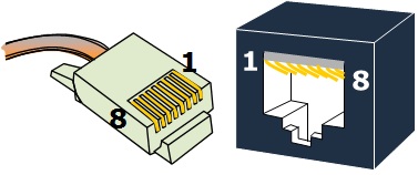
- Working place – telecommunication outlets RJ 45 (in some caces with power supply)
If you don’t familiar with elements and how they look you can visit my Gallery.
10 Gb/sec and beyond: High speed in the data center .
Ethernet, InfiniBand and Fiber Channel all have their own cable and connectivity requirements. Today growth of data centers lead to new standards for 10Gbps and above. Video-content providers, financial institutions and broadband providers demand more bandwidth and speed. Recognizing this IEEE’s High Speed Study Group recently agreed to develop a standard 802.3ba that covers both 40 and 100Gbps Ethernet speeds. Standard expected to be approved in 2010 and will be written for copper and fiber optic cabling solutions. Data rates up to 100 Gbps are envisaged to support aggregation of the data path carrying 10 Gbps, so these rates are expected to find applications in core and aggregation layer switching. The 40Gbps data rates will be used mainly in access layer applications and could also be used in high performance computing. It is relevant now to ask what types of cabling and connectors will be expected to be used at these speeds. Most data centers are a mixture of 1Gbps and 10 Gbps structured cabling system, with 1 Gbps the prevalent data rate for most data link connections and 2 or 4 Gbps for most storage link connections.
1. Ethernet 10Gbps – existing specifications.
The most economical 10 Gbps fiber network channels is 10GBase-SR channels that deploy laser-optimized 50/125 um fiber (ISO/IEC designed as OM3) with serial transceiver electronics. OM3 multimode fiber is first media options to consider because it is specified by the physical medium depended (PMD) as being able to support 10 Gbps up to 300 meters. OM3+ (extended reach OM3) is the other primary fiber choice, as both OM3 and OM3+ media can support very long reach channels throughout the network and can support future data rates beyond 10 Gbps.
The perfect transceiver for 10GBase-SR channels is the short-wavelength (850 nm) VSCEL based serial type. These low cost modular electronics are designed and optimized for use with OM3 fiber and also compatible with OM2 fiber grades. Fiber for these devices is optimized for the 850 nm wavelength window, but can also support transmissions in the 1310nm window. By default the use of serial transceivers requires the use of LC or SC connectors as the means of attachment to the fiber media.
The performance of fiber structured cabling channels depends on the ability of each channel to meet bit error rate (BER) performance requirements at minimum receiver power as specified in 802.3ae, and insertion loss of individual components within channel insertion loss(CIL) requirements. For example: the CIL budget for a 300-meter 10GBase-SR channel is 2,6dB, with 1 ,1dB allocated for the fiber media itself. Any connectors placed in the fiber path will each consume a maximum of 0,5dB to 1,0dB of the total insertion loss budget, depending of the quality of the connector system.

2. InfiniBand
InfiniBand is a scalable, high –speeds interconnect architecture that has extremely low latency. Standard InfiniBand 4X copper cables comprise eight concurrent runs (or four lines) of 100 Ohm impedance twinaxial cable that transmit at 2,5Gbps per lane to allow an overall speed of 10 Gbps. Today 4X copper twinax is used to transmit data rate up to 20 Gbps. High data rates are obtained by using more lanes and 12X twinax support up to 60Gbps. Within two years use will be made of so called Quad Data Rate (QDR) technology to support 40 Gbps over 4X cables and 120 Gbps over 12X.
Twinax differs from twisted-pair copper used in Ethernet applications in that pairs of insulated conductors are laid side-by-side and enclosed in a foil shield. The assembly operates in a dual simplex (simultaneous bidirectional) mode, where one send run and one receive run in each lane support data independently. Unlike the RJ45 connector, the InfiniBand connector is based on a precision screened and balanced edge card design.
Finally, the InfiniBand specification specifies a maximum insertion loss over the channel rather than a maximum channel length. In general signal attenuation increases as cable length increases and InfiniBand cable manufactures often use a low gauge wire (i.e. thicken conductors) to partially compensate for the higher attenuation, which results in a higher overall cable thickness and bend radius compared to twisted-pairs. This resulted in standard InfiniBand 4X copper cables having a reach of approximately 15 meters for 10Gbps data rates.
Some manufactures provide cable offerings in a variety of gauges. For example, InfiniBand copper cables with very thin gauge conductors (e.g. 30 to 32 AWG) feature a smaller bend radius for improved cable management but a very short reach of about 3 to 4 meters. Also the use of active circuitry located within the connector can improve overall link margin, which effectively increases the length of a copper cable assembly by two to three times.
Fiber InfiniBand cables are deployed in situations in witch extended –reach solutions are required. The standard InfiniBand 4X SDR fiber cable is a 12 fiber multimode 50/125 um ribbon matrix having a reach up to 200 meters and terminated with a multi-fiber array connector. Fiber cable assemblies have a smaller diameter and bend radius than copper twinax, which can offer routing and management benefits in tight data center spaces. Since most switches come with copper CX4 connectors, fiber to copper transceivers (media converters) must be attached to CX4 ports to yield these long reach solutions.
In practice, a balance of short-reach applications and cost considerations has helped copper twinax evolve into the preferred medium for InfiniBand cabling deployments.

3.Fiber Channel
The other commonly used data center interconnect is Fiber Channel for Storage Area Network (SAN) applications. Although copper may be used in the storage environment over short runs, deployment of Fiber Channel fabrics are typically based on fiber optics due to high bandwidth, small form-factor connectivity and media and wide availability.
OM3 is the first fiber grade to consider for storage areas based of recommendation in TIA 942, its ability to carry error-free 10Gbps traffic and to scale to data rates beyond 10Gbps.
Fiber links to storage areas typically are less than 50 meters, so it is possible to deploy OM2/OM2+ fiber in SAN areas and/or repurposed existing runs of OM2 fiber al less-expensive solutions than OM3.
To improve fiber Channel’s competitiveness ANSI is sponsoring two approaches based on speeds available to Ethernet through Base-T standards. The first is FC-Base-T which was designed to define the use of twisted pair Ethernet channels for the transport of the Fiber Channel information. It defines Fiber channel operation at 1Gbps, 2Gbps, and 4Gbps over Category 5e or better cabling at reach of up to 100 meters. The second approach is FCoE (Fiber Channel over Ethernet) which proposes wrapping Fiber Channel information within Ethernet frames and running it over standard Ethernet links. Both of standards are in development stage at the moment.

SDR-Single Data Rate; DDR-Double Data Rate; QDR-Quad Data Rate; SAN-Storage Area Network; CIL-Channel Insertion Loss; BER-Bit Error Rate.
With abbreviation from “Cabling Instalations&Maintenance”.
Livecicle of buildin SCS in flash…from www.ecolan.ru