


admin
AK-380 preamp out adding
Recently I have bought a very cool small chiness stereo amplifier called AK-380. It has a Bluetooth, USB and SD card multimedia imputes and also an digital FM tuner (without RDS) and a line in ( you can choose from 3.5 jack or RCA but the line in is one).

The output has very clear sound as it was rated as AB class amplifier with bass, treble and volume potentiometers on the front panel. Not the last – the price was great for such functions in one unit. The built quality is excellent , aluminum and very good quality plastic. It looks not cheap but professional.
Classical scheme of intercom system
Together with doorbells almost every building consisting of more than one floor there is built an intercom system. Currently the market offers advanced digital intercom systems in which electronic occupies a significant part. Each company offers its products and respectively provides diagrams and installation schemes.

Кey elements of which are built a classical intercom installation are carbon microphone (M) electro dynamic speaker (T) and power supply. This is one of the first circuits created and serves more to explain the principle of design of the intercom, but is fully operational.
Upon impact of sound pressure (speech) on the carbon microphone diaphragm (1) , it begins to vibrate In synchrony with these vibrations the clamping force of the carbonaceous grains (2) are changing , thereby changing the electrical resistance between the electrodes (3) and (4). When constant voltage U0 ( in the case 8V) is applied, the current through the microphone also is changing. If the microphone is incorporated into the primary coil of the transformer Tr , then in the ends of the secondary coil an AC voltage occurs , the shape of which corresponds to the sound pressure acting on the diaphragm of the carbon microphone.
Building of electrical installation for light (2/2)
Part 2: Schemes for control of lighting (lamps) by electrical switchers
Scheme 1: Control of luminaries (lamps) from simple switch
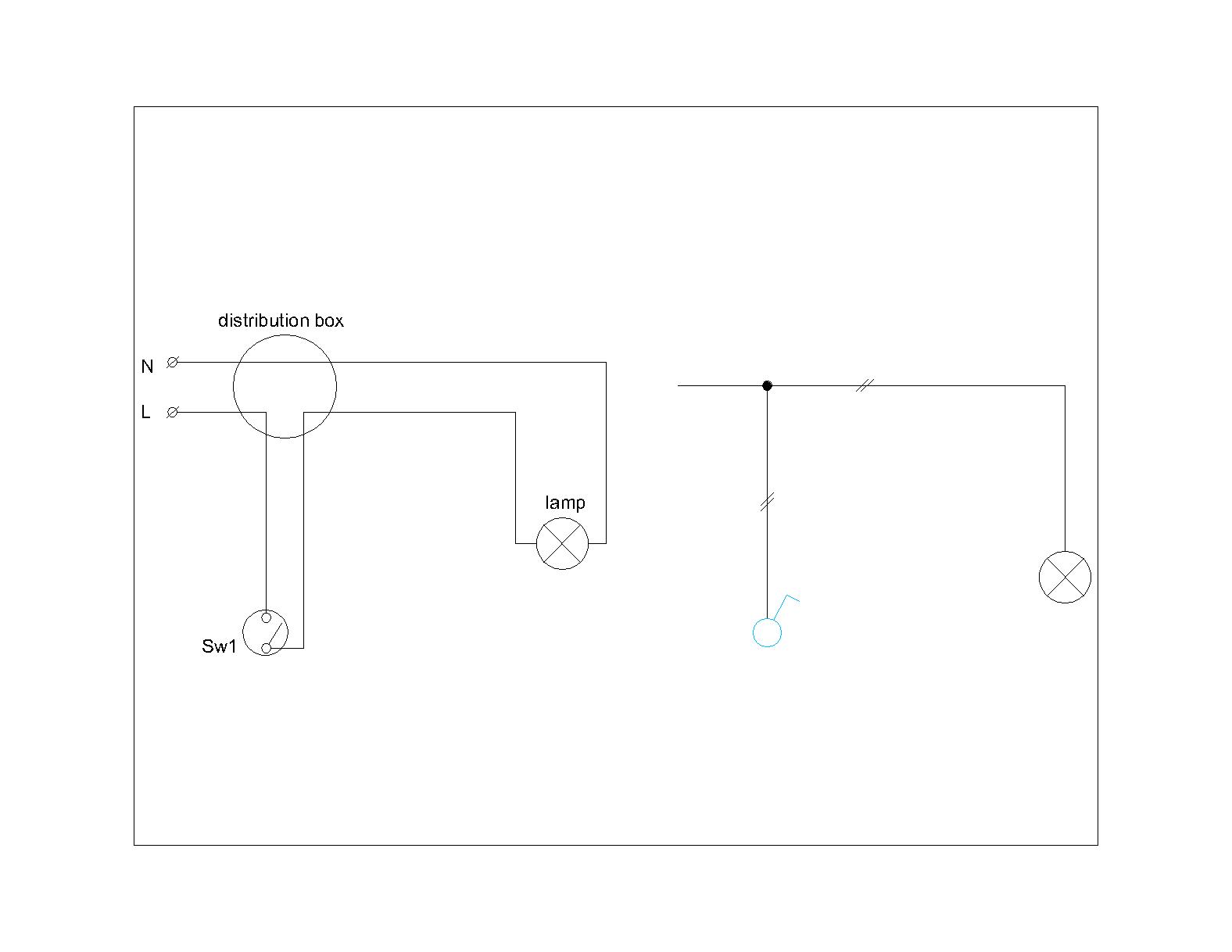
Phase conductor (L) is disconnected by power switch (Sw1), connections are made in the junction box (distribution box). When you closed the switch Sw1, the power circuit is closed and the light (lamp) lights up.
Building of electrical installation for light (1/2)
Part 1: Power cables and installation materials
In this article I will try to give the most common multi-line and single line diagrams for managing electric lighting (lamps) with installation keys. In multi lines diagrams it is showing all wiring and junction boxes. It can be said that they are more close to the mounting schemes. Single line diagrams are used in the drawings as they are drawn standardized symbols for switches, boxes and luminaries such as the number of conductors is shown with cross lines on a line symbolizing all conductors. You have to check compliance with standards and regulation in you country. In my country lighting installations in accordance with Regulation 3/09.06.2004 run directly hidden under plaster or laid in cable ducts. Under Article 1929 of Regulation 3 to power lighting systems for general lighting it uses wires with copper conductors and a cross section less than 1 mm ². Also according to Article 1876 lighting circuits shall be sized and protected by fuses or circuit breakers for the operating current not exceeding: for industrial and public buildings – 25A for residential and other buildings where maintenance of the lighting system is not performed by a specialist – 16A;
Switches, cables, junction boxes and connectors
There is widest variety of electrical switches for lighting control. Manufacturers offer different looks formed from simple to luxurious series. Each manufacturer provides user manual for wiring them. Here they will not be considered.
LAN over power supply network
Everyone is faced at least once with the problem to provide computer access point to a place that is physically inaccessible due to structural obstacles or due to unable to lay the new route (it would be broken esthetic appearance of the room). For example, you have changed your old TV with new one that has a LAN port, but when the wiring was done it is provided only electrical outlet. Another example is the situation when the cable trace that you need to build will go through someone else’s property. Possible solution furthermore to use WiFi Access Point, is to use existing electrical wiring in the home (dotted line in the picture below)

Disadvantages of WiFi is that it can not be used in places where there is strong attenuation of radio waves (2,5 GHz or 5 GHz) and require several devices to achieve good speed and strench of the signal, which is the least uneconomical.You come to the aid devices that use a transmission medium already established – the power supply grid in the home.
Incoming search terms:
lan over bt, .
Classic scheme of installation of door bell
Doorbells serve to signal the presence of a guest at the front door. In essence they are the most diverse – with mechanical bell melodic bells (e), wireless bells (e), etc. Here will be shown on a classical scheme such installation to which may be added and electron components. For example, to be replaced conventional electro-mechanical bells with electronic ones that have a variety of tunes.
Doorbells of an apartment consists of a bell placed in the entrance hall, two buttons – the front door of the apartment building (a boutonniere) and the front door of the apartment, connecting wires.

Power supply of doorbells for the entire building is performed by a general bell transformer. His classical performance is shown in Fig. 1. , the primary side is 220V/1A, the secondary side is with medium conclusion and accordingly 3V, 5V and 8V and power of 4VA. It is installed in the main switchboard at the entrance.
Wires are twisted pair of solid copper wire with insulation – PVU-A1-wire, insulation color blue and black. The temperature of the application it should not be less than -5 ° C. Section of the core is 0.5 – 0.75 mm ², the minimum bending radius is 10xD (for 0,5 mm ² D = 4,6 mm) the wires are as many as the number of apartments plus two. Both wires are common to all buttons respectively and all the bells. Installation of wires is hidden in the pipes through floors and junction boxes to buttons and bells for each apartment.
Standards for terminating of RJ45 connectors.
When network devices have being connected some cables are used terminated by RJ 45 connectors. All cables used in building of Structured Cabling Systems no matter of construction or category have four twisted pair colored in different way.
1 pair white/blue-blue;
2 pair white/orange-orange;
3 pair white/green-green;
4 pair white/brown-brown;

Incoming search terms:
T586b, rj45 standard b, .
Design of building TV (Cable and SAT) networks

Design of CATV and SAT TV
1.Cabel colective television systems ( CATV ) – Satellite television signal have recived by central equipment (recivers) after that it have been modulated in frequency range from 40 to 862 MHz . To transmite signals for fisical laeyr is used coax cabel 75 Ohms.
Design of Structured Cabling Systems

Categories/Classes in SCS
1.Cooper phisical layer– shielded and unshielded.
- Category 3/Class “C”
- Category 5е/Class “D+”
- Category 6/Class “E”
- Category 7/Class “F”
TIA and ISO comaprison of frequences, categories and classes are shown in the next tabel: Tabel 1.
| Tabel 1: TIA and ISO clasification according to frequency bandwidth | ||||
|---|---|---|---|---|
| Frequency Bandwidth | TIA (Components) | TIA (Cabling) | ISO (Components) | ISO (Cabling) |
| 1 – 100 MHz | Category 5e | Category 5e | Category 5e | Class D |
| 1 – 250 MHz | Category 6 | Category 6 | Category 6 | Class E |
| 1 – 500 MHz | Category 6A | Category 6A | Category 6A | Class EA |
| 1 – 600 MHz | n/s | n/s | Category 7 | Class F |
| 1 – 1,000 MHz | n/s | n/s | Category 7A | Class FA |
Incoming search terms:
Design of Security Alarm systems

Modern security system allowed to be conected to user and security centers through wireless, phone lines and Ethernet. Capabilities for setup of user rights, reley contacts (outs) for control, RJ45 out and software to connect with WEB interface, using proxy readers and tags. Extension with RS485 moduls for additional zones and releys.
Design of :
1.Security systems for residentials(haouse and appartments) and administartive buildings(offices)
- Control panels.
- Key pads.
- Active Infra Red Detectors(IRD).
- Passive digital and analogues IRD.
- Accoustic detectors .
- Magnetic contacts.
- Seismic detectors.
- outside and inside sirens.
2.Perimeter security systems
- Infra red bariers.
- Micro-wafe bariers.